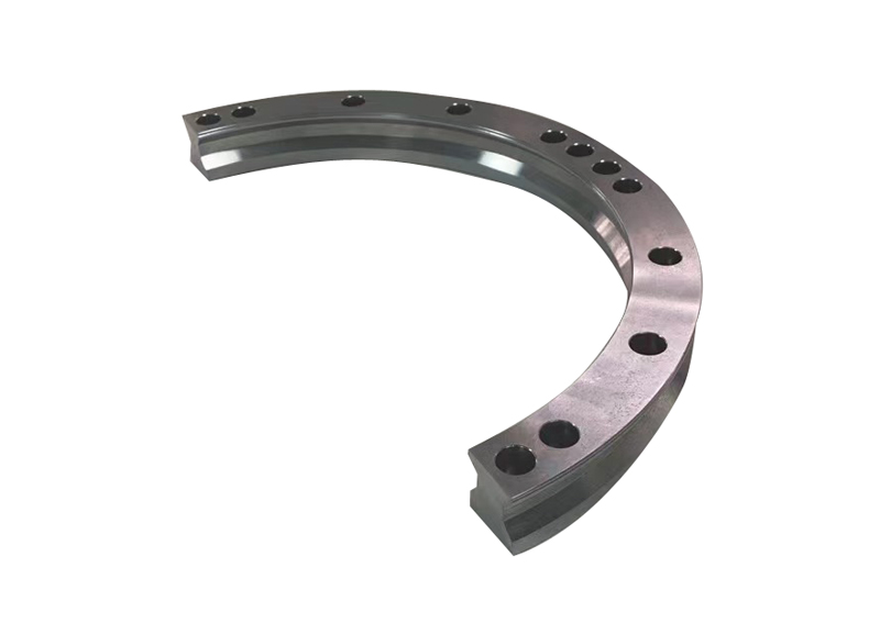
The "200" guide rail center diameter of the T23-S200 is 200mm, which is not equal to the actual footprint of the device, nor can it be directly used as the minimum installation space. During the actual layout, the outline of the arc guide rail, the maximum extension of the slide and tooling, adjacent straight sections, installation and maintenance space, and the layout range of cables, sensors and shields should be checked at the same time.
Before starting equipment design, it is recommended to download the corresponding T23-S200R90, T23-S200R180 or T23-S200R360 STEP model, and first complete the interference check in the three-dimensional assembly of the whole machine; the final manufacturing and installation dimensions should be based on the 2D/3D drawings confirmed by both parties.
The center diameter of T23-S200 is 200mm, which represents the arc diameter corresponding to the center line of the slide motion path.
However, the actual space required by the device is usually larger than this size, because the layout also includes:
• The cross-sectional width of the arc guide rail body and the mounting base plate;
• The width, length and lateral protrusion of the slide body;
• Maximum envelope of tooling, fixtures, and workpieces during turning;
• The position where it is spliced with the straight section of guide rail;
• Space for screw installation, tool operation and subsequent maintenance;
• Sensors, cables, drag chains, protective covers and other accessories.
Therefore, "center diameter 200mm" can only help engineers initially judge the tightness of the turning, but cannot replace a complete installation space calculation.
Selection suggestion: If the equipment space is very compact, first provide the existing layout diagram or the three-dimensional model of the equipment, and then confirm whether it is suitable to use the S200 arc segment instead of just reserving a circular area according to "200mm".
1. Outline of guide rail and mounting base plate
First confirm the outer dimensions of the arc guide rail body, mounting base plate and fixing screws. In addition to the guide rail itself, there should also be reserved locations for assembly tools to enter, screw removal and later maintenance.
If there are rack columns, sheet metal, cylinders or other mechanisms near the mounting surface, check whether they interfere with the guide rails and fasteners in the 3D model.
2. Maximum motion envelope of the slide, jig and workpiece
When the arc guide rail turns, what really needs attention is often not the guide rail, but the jig and workpiece above the slide.
It is recommended to confirm by "Maximum tooling status":
• Slide table size;
• The length, width and height of the fixture;
• Whether the workpiece is placed eccentrically;
• Whether the clamps, cylinders, and sensors protrude laterally;
• The maximum outer surface of the workpiece when clamped, turned over or inspected.
If the fixture protrudes far toward the center of the circle or to the outside, even if the guide rail can be installed, it may collide with other stations, guards or racks during the turning process.
3. The splicing position of adjacent straight sections and arcs
T23-S200 can be spliced with T23 straight section guide rail to form a rectangular, elliptical or other closed loop or special-shaped route.
Need to confirm when laying out:
• Whether the length of the straight section meets the work station layout;
• Whether the connection between the arc and the straight section is blocked by the frame;
• Whether installation, adjustment and maintenance are convenient near the splicing location;
• Whether the jig on the straight section has enough space to avoid before entering the arc.
For multi-station circular lines, it is recommended to first put the fixture outline of each station into the layout diagram, and then reversely deduce the guide rail route, instead of first determining the guide rail route and then forcing the work station into it.
4. Installation, lubrication and maintenance space
After the rail installation is completed, subsequent maintenance still needs to be considered.
At a minimum, you should confirm:
• Whether the fixing screws can be installed and removed normally;
• Whether guide rail cleaning, inspection and lubrication maintenance can be carried out;
• Is there a disassembly path when the carriages or fixture fails?
• Whether there is operating space after the protective cover is opened;
• Whether maintenance personnel need to access the arc segment from the inside or outside.
Compact equipment often suffers from the problem of "fitting in, but not maintaining". It is recommended to reserve maintenance access during the layout stage rather than waiting for the equipment to be installed before changing the rack or shield.
5. Space for cables, sensors and safety shields
If the slide base is equipped with air lines, cables, sensors or actuators, check the actual range of movement of the cables and accessories.
Special attention should be paid to:
• Whether the cable bending radius meets the requirements;
• Whether the drag chain or wire harness is squeezed or pulled when passing through the arc;
• Whether the proximity switch, stopper and positioning components interfere with the fixture;
• Whether the guard covers the movement area while retaining access openings;
• Whether the personnel operating area is kept at a safe distance from moving parts.
This part is often not reflected in the guide rail STEP model and needs to be confirmed by the equipment designer in conjunction with the electrical and safety plans.
T23-S200 is available in 90°, 180°, and 360° arc angles. Which one you choose depends on the equipment route and work station distribution.
arc form
Common layout uses
Key points to check
R90
Right-angle turns, rectangular route corners
Jig envelope inside and outside corners, connection of adjacent straight sections
R180
U-shaped rotation, double row reciprocating layout
Spacing between two straight sections and maintenance space at the rotary end
R360
Circular circulation, compact carousel layout
Occupation of central area, interference of inner and outer ring fixtures, loading and unloading positions
Copy table
Expand table
When selecting the arc angle, don't just look at whether the guide rail path can be put down, but also confirm the maximum sweeping range of the workpiece during the turning process.
For example, R90 is suitable for connecting two straight sections of workstations; R180 is more suitable for double-row layouts that require rotation; R360 can form a complete cycle path. If the standard angle cannot match the on-site route, the actual radius, angle, number of slides and center distance can be provided for confirmation of the non-standard solution.
Mistake 1: Only press "200mm" to reserve space
The center diameter is not the outline of the guide rail, nor is it the area occupied by the entire equipment. If you only draw a circle based on 200mm, it is easy to ignore the guide rail section, carriages, tooling and maintenance space.
Mistake 2: Ignoring the extension of the fixture and workpiece
It is often the jig, fixture or workpiece that actually interferes, rather than the rail itself. The motion envelope should be established according to the maximum working condition, and do not just look at the unloaded slide.
Mistake 3: Ignoring installation tools and subsequent maintenance
If the fixing screws are blocked by the frame, or the slide cannot be disassembled or assembled after the guard is opened, subsequent maintenance costs will increase significantly. Installation and maintenance locations should be reserved simultaneously during the layout stage.
In order to complete the preliminary judgment of T23-S200 arc guide rail faster, it is recommended to provide the following information:
1. Overall equipment layout diagram, on-site photos or three-dimensional model;
2. Plan to use R90, R180, R360, or the desired arc radius and angle;
3. Whether it needs to be spliced with T23 straight section guide rail;
4. The number of slides, center distance and the function of each station;
5. Total load of a single slide, including workpiece, jig, fixture and mounting plate;
6. The maximum outer dimensions, center of gravity and eccentric load of the workpiece and fixture;
7. cycle time, operation mode, positioning requirements and start and stop frequency;
8. Installation surface size, surrounding racks and available maintenance space;
9. Are there environmental requirements such as moisture, corrosion, dust, and cleanliness?
10. CAD files. Priority is given to providing STEP, DWG, and DXF; if 3D files are not available, PDF or sketches with dimensions are also acceptable.
6. Conclusion: Do assembly check first, and then confirm the manufacturing plan
T23-S200 arc guide rails are suitable for compact turns and closed-loop routes, but "installability" cannot be judged solely by the center diameter. Only by putting the guide rails, slides, jigs, tooling, straight sections, maintenance and cable spaces into the same layout model for verification can the risk of later modifications be reduced.
T23-S200 supports 90°, 180°, and 360° arcs, and also supports splicing with T23 straight section guide rails; you can first download the STEP model for preliminary layout verification, and then submit the actual working conditions and drawings for confirmation.
The 200mm of T23-S200 is the center diameter of the guide rail, not the minimum installation size; the actual space should be confirmed with the STEP model to check the guide rail outline, fixture motion envelope, maintenance and cable area.
•T23-S200 arc guide rail product parameters and STEP drawing download
• How to choose circular guide rail? Load, turning radius and repeatability
• How to choose the circular guide rail driving method? Comparison of four drivers

Precision conveying systems · Products and service
Products
Chain-driven ring guidesBelt-driven ring guidesPrecision link conveyorsCurved and linear guide componentsMagnetic levitation conveyorsCam-link ring guidesAbout us
Company profileOur facilitiesCertifications VideosApplicationsApplications
Automotive & new energy Precision electronics assembly Consumer electronicsMedical devicesNew energyPrecision dispensingNews
Company news Industry news NewsContact us
Contact details WhatsApp Business
Contact details+86 18912659251
Links: